What you’ll learn
This article is part of the Camper Van Conversion series and details the major parts for your camper van’s electrical system and how they interact to function as a house-on-wheels. The next article in the series will describe how to actually build the physical system and get your hands dirty. Our specs:
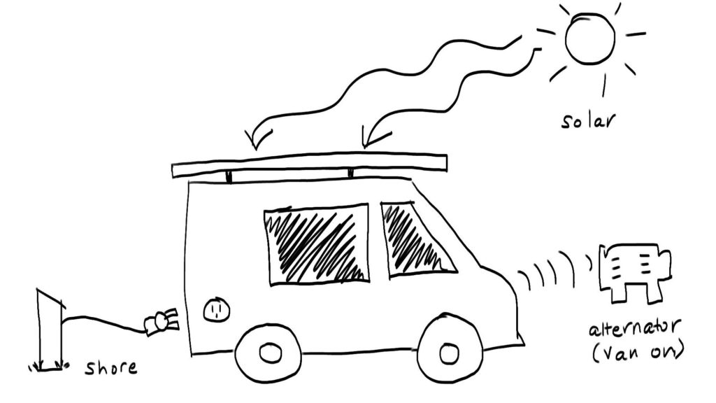
- Battery: 300Ah 12V AGM (2x 300Ah 6V in series)
- Charging sources: solar, shore, alternator. We have 4x 100W solar panels. When the engine is on, it’ll charge our battery bank from the alternator, but a failsafe is in place to prevent our battery bank from discharging our starter battery. Shore charge is via typical RV plug-ins at 110V/15A or 30A.
- Loads: AC and DC systems. Loads include LED ceiling lights, external LED lightbars, water pump, water heater, diesel air heater, refrigerator, inverter for AC system, electric tea kettle, hair dryer, AC and DC plugs for phones/laptops/etc. Many components in your van will need DC.
This post contains affiliate links. I’ll receive a commission fee if you click on a product link. Your buy price doesn’t change, but the commission I receive from the retailer goes to the maintenance and hosting costs of this website.
Loads: Sizing Your Battery Bank
In researching camper van electrical systems, you can get trapped into a lot of details on how much power you’ll use, but in reality, constraints like cost and space will affect your decision more. Go with more battery than you think so you can last for more than a day without charging.
We went with 2x AGM 300Ah 6V batteries in series, for 300Ah 12V. AGMs were $750 vs Lithium at $3000 (in 2019). However, each AGM is 10″x7″x13″ and 90lb.
150Ah usable battery is sufficient for 2 people for 1 day with no charge. This is for normal living, using lights, refrigerator, air heater, water pump/heater, fans, 2x laptops and 2x phones, cell signal booster, coffee maker. We can’t do 2 consecutive full-load days without a significant charging source.
Here’s a sample breakdown of the loads we have, mostly to illustrate of how they add up quickly. 150Ah should be a sufficient minimum to be comfortable, unless you have a specific need–we’ve seen Instant Pots used in vans!
| Load | Watts or Amps | Time per Day | Ah per Day |
|---|---|---|---|
| 8x LED ceiling lights | 0.2A | 5hr | (0.2A)(8)(5hr) = 7.2Ah |
| 2x LED outdoor | 20W | 1hr | (20W)(2)(1hr)/12V = 3.3Ah |
| Refrigerator | 6.2A | 3hr | (6.2A)(3hr) = 18.6Ah |
| Diesel air heater | 3A | 4x 30min cycles | (3A)(2hr) = 6Ah |
| MaxxFan fans x2 | 0.2A | 5hr | (0.2A)(2)(5hr) = 2Ah |
| Cell booster | 1A | 5hr | (1A)(5hr) = 5Ah |
| Phones, Kindle, camera, batteries | — | — | (3Ah phones)(2)+ (1.5Ah kindle)(2)+ (1.3Ah camera battery) = 10.3Ah |
| Inverter (needed for all AC charging below) | 2.5A | 6hr | (2.5A)(6hr) = 15Ah |
| Water pump + water heater (AC) | 242A (all heater; pump negligible) | 5min | (242A)(5min) /(60min/hr) /(0.9) = 22Ah |
| Laptop batteries x2 (AC) | — | — | (6.7Ah)(2) = 13.4Ah |
| Water kettle for coffee (AC) | 1500W | 5min | (1500W)/(12V)* (5min)(60min/hr)/ (0.9) = 11.5Ah |
| Total: 114.3Ah |
Notes on the above table:
- Power = Current * Voltage
- Current = Power / Voltage. To calculate the Amp-hours needed per day, take the power, divide by 12V (for a 12V DC battery), and multiply by the hours used per day.
- Assume DC loads unless specified otherwise.
- Some of the Watts/Amps are directly from the user manuals, others are actually measured using our battery monitor app.
- The inverter needs to be on for any AC load, which adds an additional 2.5A to the AC load draw. The inverter’s efficiency is 90%, so divide by 0.9 for AC loads to find the effective battery energy consumed.
- To calculate AC Amp-hrs per day: take the power in watts (power draw is the same in AC or DC; it’s just total power regardless of how it’s supplied), divide by 12V (since we’re figuring out current from the DC battery bank), multiply by total hours running per day, and multiply by 90% efficiency.
Rule of thumb is to not let AGM batteries drain below 50%; that reduces the number of charge cycles in its life. So, if you want 150Ah of usable battery and go with AGMs, you need 300Ah.


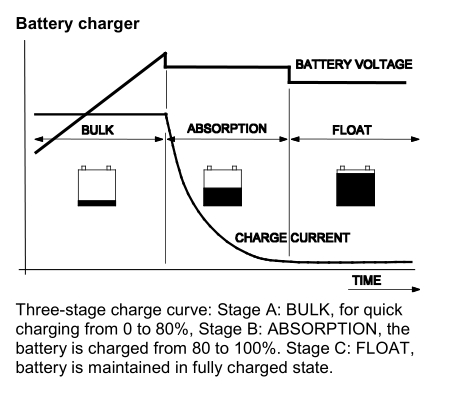
How a battery likes to be charged
It shouldn’t be charged at full speed–there’s typically 3 phases: bulk, absorption, and float. When you’re low, like <80%, it should be charged quickly in the bulk phase with max current and increasing voltage. For the last 20%, it should be charged in the absorption phase, with constant, slightly lower voltage and decreasing current. This means that if you’re at 90% battery, it’ll take more time to get to 100% than it would from 50% to 60%. Float charge maintains the top-off.
So how do the 3 charging inputs (solar, alternator, shore) charge the battery such that the battery’s happy? Each charging source has their own control “brain.” These charge controllers convert the output voltage and current of the charging source to the appropriate voltage and current to charge the battery. Each controller should have presets for AGM or Lithium batteries that set the bulk, absorption, and float charging voltages, or you override those manually. The simplified charging system looks like:
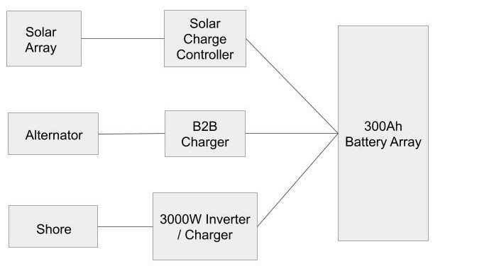
The solar array needs a solar charge controller; the alternator needs a B2B (battery-to-battery) charger; shore power needs an inverter/charger. Let’s dive into each one before we tackle how they compete/compliment each other in real-life scenarios.
Charging from Solar
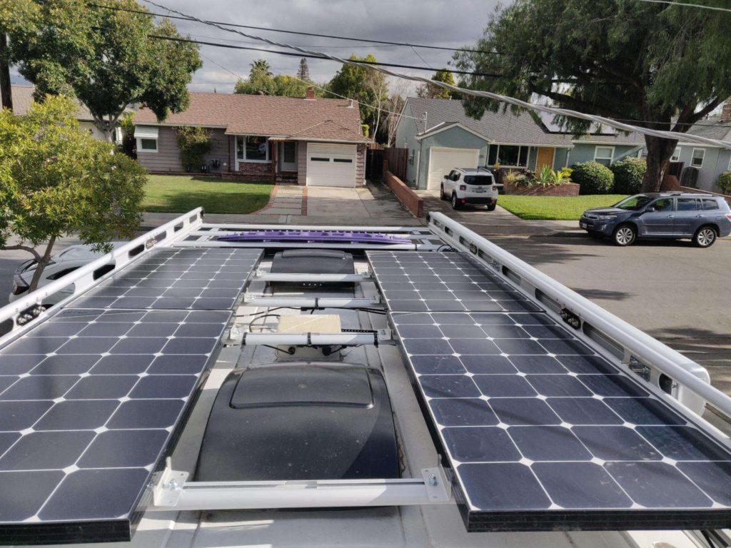
If you’re charging >=150Ah of effective battery, you’ll want to max out on the solar panels; solar will be the limiting factor compared to a battery bank. You’ll be limited in roof space depending on where your fans are located, which will dictate which solar panels are viable options for you.
In theory: Charging 150Ah of a 12V battery is 1800Watt-hours (150*12) of total energy needed. With 4x 100W solar panels, it would take 1800Wh/400W = 4.5hrs to fully charge under perfect conditions.
In practice: There’s loss due to the efficiency of the solar charge controller (the thing that sits between your solar panels and battery bank), you won’t get full 90-degree sun all day, you’ll get partial shade due to trees, it’ll be overcast, your panels will be dirty. We get ~25% of the theoretical max on a winter day with some partial shade (~400Wh instead of theoretical 1800Wh, or 400Ah/12V = 33Ah charge, much lower than our >100Ah/day use).
So, get as much solar as your roof configuration and pocketbook will allow.
Series, parallel, or series-parallel? Series has the pro of having the smallest current (it’s the current, not the voltage, that’ll kill you–literally), but partial shading will drastically cut down the output (think of old Christmas tree lights when one went bad). Parallel is great in that every panel is independent, so partial shade on one won’t hose the whole circuit, but the amperage is huge to transport via wire a long way (you’re going from roof back to the electrical box), and the controller needs to handle much larger current.
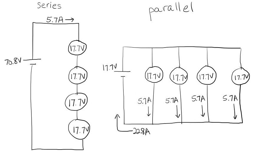
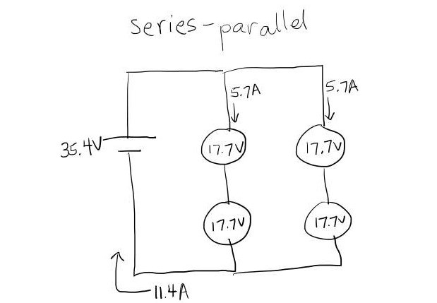
We went with a series-parallel configuration. Based on Renogy’s solar cable calculator (the brand of our solar panels), the ideal parallel configuration above would need 6 AWG wire (using 18V, 25A, and 20ft length run approximations). Finding 6 AWG solar connectors and that thick of wire wasn’t feasible. The series-parallel configuration requires 12 AWG according to Renogy’s calculator (using 36V, 12A, 20ft approximations). We went with 10 AWG. Note that Renogy requires a thicker wire than other online calculators like Blue Seas, but it’s wise to go with the manufacturer’s recommendation.
Renogy 100W/12V Eclipse Monocrystalline Solar Panels
We have 4, hooked up in parallel-series. Renogy makes excellent panels, their help center tutorials are great, and they’re some of the most efficient on the market. They fit RV roof racks well.

Victron SmartSolar MPPT 100V/20A with Bluetooth
This is the smart solar charge controller that sits between the panels and your battery bank. It connects to your phone via BT app and is excellent at real-time monitoring. Very highly recommend springing the $ for the smart version. You also want MPPT, not PWM–they’re ~20% more efficient.

Charging from Alternator
We travel mostly in the fall when weather and sun angle aren’t optimal, and there’s stretches of days that solar provides hardly any meaningful charge. For the most robust camper van electrical system, charging from the alternator is required, if you don’t pay $$ for a campsite with electrical hookups.
Charging from the alternator is actually quite simple. You wire your alternator to a battery-to-battery (B2B) charger, which takes power from the alternator when the engine is on, regulates the voltage and current, then sends the appropriate charge to the battery bank. It will have a one-direction flow, so if your battery bank is low, it won’t deplete the starter battery.
In theory, a 60A B2B charger pulling from a 12V battery via alternator will yield 60A*12V = 720W. At the output, this will translate to ~14V to charge the battery, or 720W/14V = 51A. To charge 150Ah, that’d be about 3hrs. It’s pretty close in real life, although it takes much longer to get that last 10%.

Charging from Shore
This is the typical RV-plug-in. It comes in handy when you happen to be at a full campground site or someone’s house. The charge source is AC, so it goes first to the inverter/charger to be converted to DC before charging the battery.
You’ll need an inverter anyways to power any AC outlets, so you may as well spring a little more for an inverter/charger to get shore power.

How Charging Sources Interact Simultaneously
So how do the 3 charging inputs (solar, alternator, shore) compete/compliment each other in everyday scenarios?
There’s no single master brain controlling the charge state to the battery. Each of the Solar Controller, B2B Charger, and the Inverter/Charger have their own independent ability to produce the optimal output voltage and current for the battery’s state.
Each of your controllers should have a battery preset (e.g. AGM, Lithium) for the voltage at which they charge in Bulk, Absorption, and Float, and they should be configurable. Think of the sources as pressurized water pipes (water=current) and the battery as a holding tank. If the tank is pressurized at 10psi, and you have input pipes at 12psi and 13psi, both will fill the tank. If your tank is pressurized at 10psi, and you have input pipes at 9psi and 11psi, only the 11psi pipe will fill the tank.
| B2B Controller | Solar Controller | |
| Bulk | voltage increases until hits absorption setpoint | voltage increases until hits absorption setpoint |
| Absorption | 14.6V | 14.4V |
| Float | 13.7V | 13.8V |
Take the above example. If your battery is at 50%, and you’re driving down the road with solar on, both solar and the alternator will charge the battery. When the battery reaches 14.4V, the solar controller will back off into absorption, and the alternator will continue to bulk charge until 14.6V, then back off into absorption as well. If your battery is almost charged and it’s a cloudy day, solar is likely not going to charge at all since the battery voltage will be greater than what solar is producing (but the solar charge controller will protect against back-flow).
Note: Invest well in the controllers. If you decide to upgrade your solar panels or batteries down the road, you can keep well-spec’ed controllers.
AC and DC load systems
You’re going to have to wire your van for both AC and DC. You want everything you can run off of DC so you don’t need to run the inverter, because remember the inverter takes 2A to run; at 6hrs a day (like you’ve got your laptop plugged in), that’s 12Ah, or 8% of 150Ah usable battery!
Marine/RV refrigerators, water pumps, LED lights run off of DC. You can hook these loads to the battery’s positive and negative terminals [via DC breaker]. The AC loads like outlets and water heater need to be hooked up to the inverter/charger [via AC breaker].
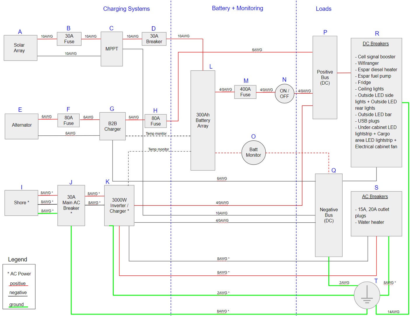
Camper Van Electrical System Diagram
I have to say that between my Electrical Engineering degree (go Rice U!) and Jeremy’s practical know-how, this is a pretty darn solid system, after researching dozens of sites and spending hours double-checking ourselves. Many setups we’ve seen on YouTube and the web aren’t safety-sound; e.g. we’ve seen 3000W inverters mounted directly to plywood and failing to fuse early enough in a circuit, posing serious fire and electrical risk.

- The 3 charging sources are A, E, and I. Each go through their own controller C, G, and K (e.g. MPPT solar charge controller) before going to the battery.
- Fuses are B, D, F, H, M. These are critical to protecting the system from overload.
- The B2B charger G and Inverter/Charger K have temperature probes on the negative battery terminal, which give feedback on what rate they should charge the battery.
- The battery monitor O runs all the way back to our control panel in the doorway. It also connects via Bluetooth app to our smartphones.
- There’s a master On/Off switch N. This kills all DC in and out of the battery. We’ve left the solar charge out of this switch and opted to put a dedicated solar breaker D instead. This allows us to kill everything except solar charging while still having it parked in our driveway for long periods, so that the battery bank maintains a charge. To kill everything, we turn off D and N.
- The logical diagram of the loads (what would be to the right of the breakers) isn’t shown.
- DC circuit negative is the same as ground, often called “common.” Green connections in the diagram are AC ground, Black connections are negative (for AC) or common (for DC).
→ Explore more articles in Camper Van